Everything you always wanted to know but were too afraid to ask about Paperspace:
Paperspace and Layouts are the interface between your model and the plotter. They are critical for efficient communication but often poorly understood. Here is a brief outline of what you need to know.
This is a discussion rather than a tutorial and assumes that you have at least used Paperspace before but are just a tiny bit confused. You should also visit and work through relevant tutorials. A good source is myCADsite.com.
Topics reviewed:
Viewports, Vports, Mview, Modelspace, Paperspace , Tilemode, Model-Tab, Layout-Tab, Vplayer, Workspace, Views, Viewpoints, UCS, Workzones
Beware of Metaphors:
The big problem with understanding Paperspace and Modelspace lies with the metaphors used to explain it. “Windows onto the World”, “Picture frames” etc. perpetuate the imprecise metaphors used to explain CAD as a whole. How often have you read that a Layer is like a “transparent overlay”? Useful up to a point but it is much better to understand that a Layername is a property given to individual objects (albeit by drawing them on or changing them to a defined Layer) rather than a transparent sheet with objects drawn on it. This is a particularly misleading metaphor as it gives the impression that a Layer is a collection of objects (as though it were a slice through the model) rather than setting the properties of the objects. "Layer" is in effect a poor use of terminology. Preferably think of it as a definition of object properties .
Quite unrelated to Layers but in similar manner efforts to explain Paperspace also mislead. The metaphors of “paper space” and “model space” can be confusing because “models” can be created in both model space and paper space and what we often think of as Paperspace contains Viewports of Modelspace thus: drawing sheets are models drawn in paper space, and model space models can also be edited from within paper space by activating Floating-Viewports. There is also the concept of Layouts to further complicate things.
A bit of history:
When first published, AutoCAD had only one drawing environment. It didn’t have a name then, but due to the later introduction of Paperspace, it became called Modelspace to distinguish it from the new paper space. Modelspace can be used either as one single viewport or be subdivided into multiple Viewports. (Command: VPORTS). In Modelspace the Viewports, regardless of how many, always totally fill the screen rather like tiles on a wall; hence Modelspace was described as Tilemode ON (1). On the other hand when Tilemode is OFF (0) Viewports can be anywhere any size any shape, i.e. Not “tiled”.
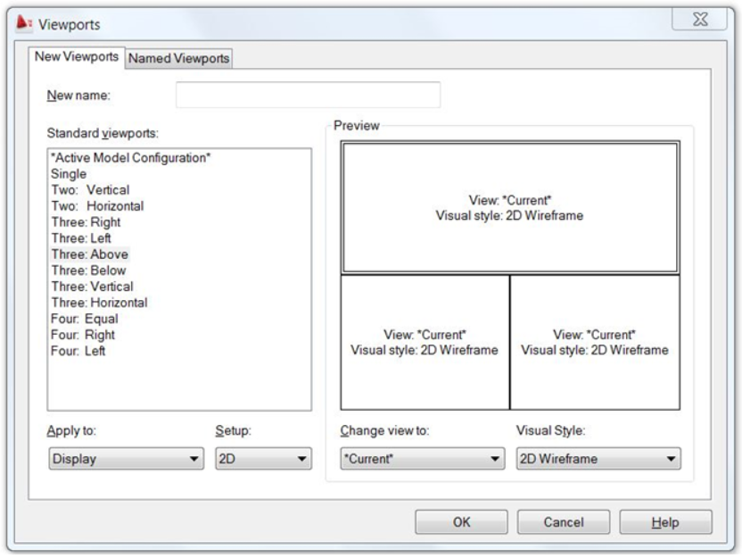
Creating multiple “TILED” Viewports. Tilemode ON (1)
Drawing in a pre-Paperspace environment:
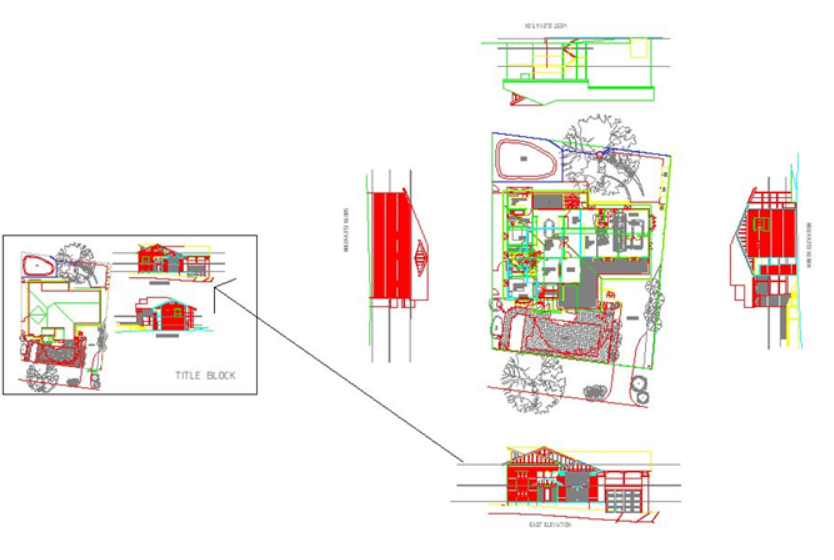
In pre-Paperspace days we drew all of our plans, elevations, details etc. as well as drawing-sheet outlines and title-blocks as sub-models spread around all within the one environment (Modelspace) and then later re-arranged them (in that same environment) into drawing-sheets ready for plotting.
Smart operators created BLOCKs of the various sub-models and then INSERTed these scaled BLOCKs into the outlines of drawing sheets rather than moving, re-scaling and rotating the sub-models themselves. That way the various views (top, left, right etc.) could be retained as and where they were drawn and the Blocks could be rotated and scaled upon insertion to suit the drawing sheet(s) layout.
Alternatively the sub-models and the drawing-sheet outline could be drawn in separate files and brought together for plotting by inserting the sub-models into the drawing sheet (using the INSERT “=” option if necessary to update any existing blocks.)
Blocks are made of sub-models and then inserted into drawing-sheet outlines for plotting.
The new Paperspace provided a way of arranging Viewports that could now be any size any shape and in any position and display views of the model at any scale or rotation or in any layer condition . They may be overlapped and even contained one within another. All of the user-created “floating” Viewports are in fact contained within viewport No.1 that is the whole screen.
Multiple Viewports are just different ways of displaying the same model or different parts of the model from different points of view by controlling view-point, view-distance, view-area and layer-state. We can also control front and rear clipping planes or depth-of-field. Every viewport, floating or tiled, including viewport 1 can be zoomed, panned and have different viewpoint angles except viewport 1 that can be zoomed and panned but has a fixed viewpoint perpendicular to the X/Y plane.
To further complicate things the condition of Tilemode 0 (Paperspace) is now called a Layout (space) of which there can be multiple occurrences.
Floating Viewports in Tilemode 0 showing the model from the same point of view but with layers controlled by VPLAYER command to display different aspects of the building.
Advantages of Paper Space:
The special properties of the new Tilemode OFF (0) are:
-
Floating Viewports can be any shape or size and located in any position making it easier to arrange different views of the model for plotting.
-
We can have spare space around the floating Viewports in which we can draw further models, such as drawing-sheet outlines, title blocks and view labels etc. in relation to the floating Viewports. This space is itself a viewport called viewport 1 that occupies the whole screen. User-created Floating-Viewports are numbered 2, 3, 4 etc. and appear within viewport 1. (Contrast with the “tiled” option).
-
The VPLAYER command allows layer settings to be controlled per floating viewport so that different aspects of the same model can be concurrently displayed in different Viewports
Using Paper Space:
In all cases only one viewport at a time (including viewport 1) can be active. This is done by double-clicking within the selected viewport. Viewport 1 is selected by clicking clear of floating Viewports. Viewports fully contained within another viewport (other than viewport No.1) cannot be activated because the enclosing viewport will take precedence.
When Tilemode is 0 switching into and out of Floating-Viewports can be achieved by using the PSPACE and MSPACE commands but both commands are invalid when Tilemode is 1, because you’re already in Modelspace and there aint no paper space to switch to. So how do you get back to Tilemode 0 from Tilemode 1? Answer: either by entering the command Tilemode 0 or by clicking on a Layout Tab or Icon. Then you are back to floating-Viewports and Tilemode 0.
Model and Layout Tabs if not present can be enabled by going to Options – Display – and checking “Display Layout and Model Tabs”.
When Tilemode is 1 the command to make multiple view ports is VPORTS. When Tilemode is 0 the command to make a viewport is MVIEW, (Model-VIEW or Make-VIEWport I’m not sure). Note that if you have more than one Viewport in TTilemode 1 only the active one will appear in Tilemode 0.
Confusing? Well! Let’s try to put it another way. In Tilemode 1 you can only draw models in Modelspace whereas in Tilemode 0 you can draw in either Modelspace (inside an activated user created Floating-Viewport) or in Paperspace (Tilemode 0’s viewport number 1).
Layouts:
The ability to create multiple Layout Tabs implies that you should use one Layout Tab per drawing sheet but it is equally possible, and often preferable, to setup multiple drawing sheets in the same Layout. Whatever your choice, the common implication is that Layouts generally include drawing-sheet outlines, title information, view labels etc. in Viewport 1 and models in Viewports 2, 3, 4 etc. representing drawing sheets ready for plotting.
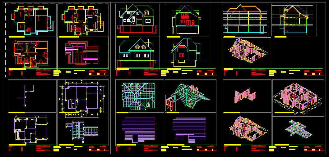
IMAGE
Multiple drawing sheets in the same Layout can be easier to manage than multiple layouts of one sheet each.
What belongs in paper space?
-
Only put in paper space that which belongs to the drawing-sheet; outlines, title-blocks, view-labels, general notes, amendment notes, north-point etc. NOT dimensions or text that belong to the model. (Author’s opinion) It could be debatable whether or not view-labels (“EAST ELEVATION” etc.) should be part of the model or part of the sheet?
-
It is handy to have view-labels in both Modelspace and Paperspace to enable quick recognition of views while editing in Tilemode 1 but they are not really part of the model and it is easier to set out the drawing sheet if the labels are part of the drawing sheet.
-
Duplicate Labels in model space should have a NON-plotting layer assigned to them so that they can be turned off in Layout space and not show up in drawing plots.
-
Some operators argue that dimensions and text should be part of the drawing sheet presumably because they are not strictly part of the model and putting them in Paperspace overcomes the problem of having to calculate the different text sizes and dimension scales required by the zoom factor of the various floating Viewports. Just because AutoCAD provides this option does not make it a good choice. This is a discussion that I will reserve for another time
Suggestions:
-
Unless you have keyboard-shortcuts to switch between Tilemode 1 and 0 use the Model and Layout tabs.
-
Normally you would edit your model in Tilemode 1 but you can also edit a Modelspace model by activating a Floating-Viewport in Tilemode 0.
-
Multiple drawing sheets in the same Layout can be easier to manage than multiple Layouts of one drawing-sheet per Layout.
-
If you do decide to edit within a floating viewport be aware that:
-
Unless the viewport is locked you may upset your zoom and pan conditions.
-
Some layers may be VPLAYER frozen and thus be excluded from editing.
-
Editing within floating Viewports in Tilemode 0 involves a lot more zooming and panning than working directly in Tilemode 1.
-
Editing Tilemode 1 objects may be complicated by related dimensions and text placed in Tilemode 0.
-
-
AutoCAD seems to suggest that you should use one Layout per drawing sheet, but you should consider using a single Layout with multiple drawing sheets as this can give a better understanding of the drawing sheets in the file and can reduce the amount of work preparing for plotting but at the possible cost of limiting automated plotting functions.
-
Recent versions of AutoCAD offer “ANNOTATIVE” dimensioning in Layout space as an alternative to directly relating dimensions to the model in model space. This generates both a philosophical and functional discussion. You should decide for yourself based on the type of work you do but for me at the moment I am going to stick to keeping model related annotations and dimensions in model space relative to the model.
WORKZONES:
WORKZONES is a unique new concept provided by MYCADLAYERS, a third-party AutoCAD add-on. It provides powerful techniques that permit efficient overlay-drafting. Multilayered composite models are easily constructed and revealed for editing and plotting using automated processes that manage not only Modelspace but also automatically resolve layer visibility in Paperspace.
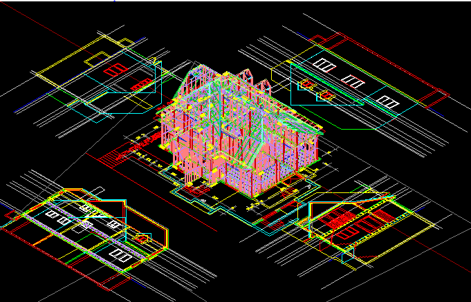
IMAGE
A multi-layered 3D model with 2D elevations projected in model-space (Tilemode 1) before arranging into drawing sheets.
Reader Comments Please:
So many people express difficulty with paper space that it is worth asking your opinion so that this article can be improved:
-
What is it about Paper Space that you find difficult?
-
Did these notes help you to better understand Paperspace v Modelspace?
-
Can you suggest additions or improvements to these notes?
-
What other subjects would you like to be similarly addressed?