WORKSPACE vs WORKZONE
Do not confuse AutoCAD's "WORKSPACE" command with MYCADKEYS “WORKZONE”.
Workspaces are about the drawing production environment created by the drafter to facilitate the drawing process. Workspaces use UCS origin, viewpoint, layer visibility, zoom factor etc to assist the drafter. Changing the Workspace does not affect the target production drawing.
Workzones are a MYCADKEYS concept (devised long before AutoCAD introduced “Workspace”) that define specific aspects of the drawing model including area, viewpoint, level, layer visibility etc chosen to display finished production drawings. An example drawing might be "plan, west-wing level-three, electrical,.
Autocad's MVIEW and MVSETUP commands can go part way to defining an area of the drawing model for plotting but is dependent on separately setting specific layer states.
Coincident Overlay Drafting is a technique used in 2D drafting that allows composite data models to be created combining multiple levels or sections (slices) of a building or three dimensional product superimposed in the drawing environment so that related views are overlaid but may be separated as required by layer control.
MYCADLAYERS provides automated functions to create correct layer-names and control their visibility by WORKZONE.
Coincident Overlay Drafting:
-
Produces more intelligent and more accurate drawings.
-
Reduces Time In Drawing.
-
Aids editing, viewing and printing.
-
Reduces drawing file size.
-
Reduces number of files.
-
Improves file management.
WORKZONEs are quite distinct from AutoCAD's Workspace, LAYERSTATE and SHEET-SET concepts; all of which are made virtually redundant by MYCADZONES.
MYCADLAYERS uses the last six characters of 12 character layer names to identify the drawing type, view point and specific view that objects with that layer name belong to.
MYCADLAYERS is able to automatically filter layers by name into specific WORKZONEs. This facilitates the process of combining multiple drawing types and multiple plan, section or elevation levels in a single model by using Layer control and OVERLAY drafting to selectively view, edit or plot individual drawings.
MYCADLAYERS generates and manages layers semi-automatically according to the function and level of the drawing being created so that an entire model can be built in the one location while keeping each level and drawing type individually visually separate. This is similar to the concept of using the VPLAYER command in Tilemode zero (Paperspace) to control the visibility of layers within the floating Viewports but applies also to Tilemode 1 (Modelspace). Information can be both separated and combined level by level and drawing function by function. The big difference between MYCADZONES and generic AutoCAD layer management is that this is all automated using single commands to create layers and resolve layer visibility in both Paperspace and Modelspace while keeping the entire model as one unified co-located collection of drawing objects. The ability to view and edit multiple levels and drawing types concurrently allows checking of alignment and interaction of drawing objects. An added benefit is the ability to copy one floor level to another while automatically adjusting layer names with a single command.
A typical MYCADLAYERS command is LR (Layer Resolve) that prompts the user to enter layer field codes for Drawing-type, View-Point and view-ID and will then freeze and thaw relevant layers to reveal the required WORKZONE of the drawing.
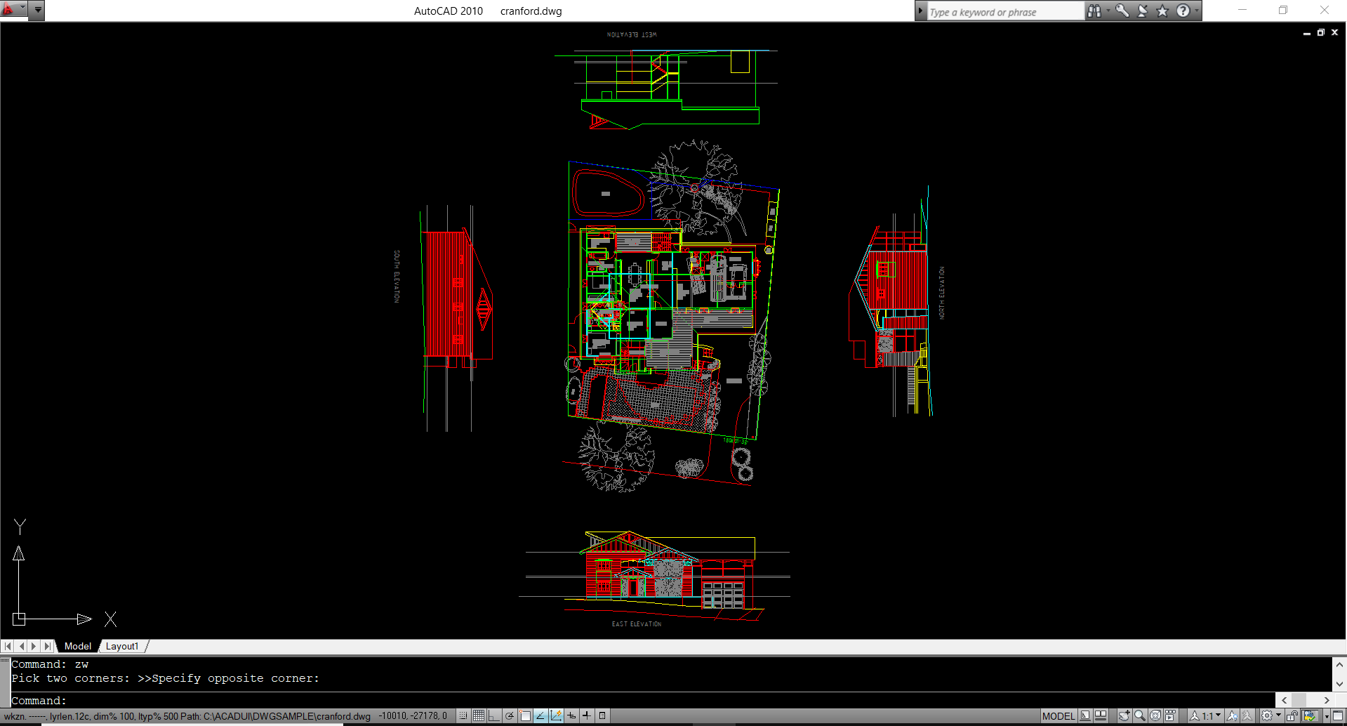
Full model showing all plans, sections and elevations with all layers ON and Thawed.

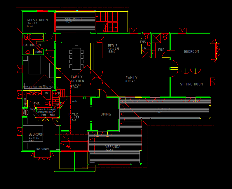
Same file with a single Floor Plan - WORKZONE resolved.

Same file viewed in Layout / Paperspace / Tilemode 0 with all views/drawings/WORKZONEs displayed for printing.

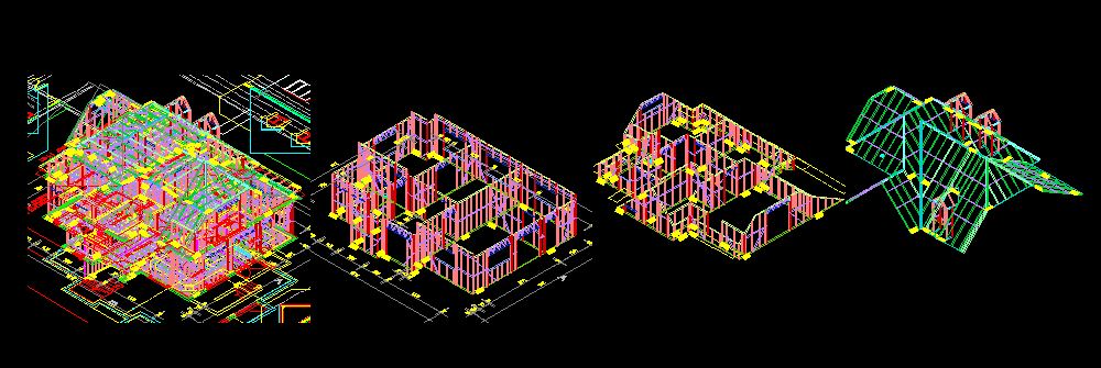
Same model with all levels (displaced vertically for illustration purposes) to demonstrate the contents of the single model.
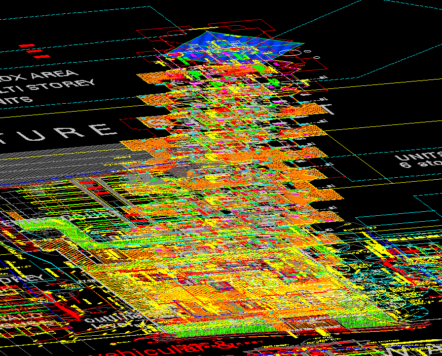

WORKZONES are not necessarily flat sub-models as can be seen from this 3D light steel frame house design. (views separated for display purposes)
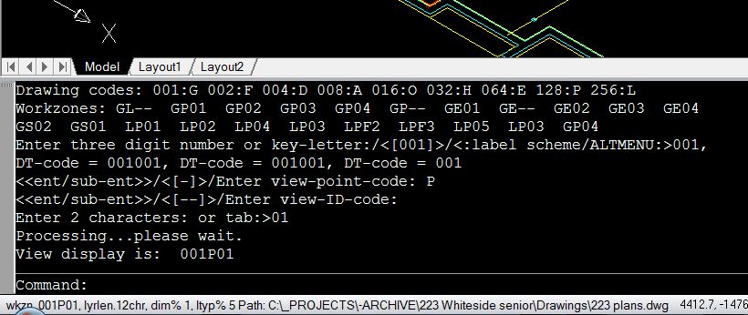
Status (Command-line) displays instructions for use of MYCADZOES and MYCADLAYERS functions,
In a crowded drawing environment it might also be convenient to allow elevations and sections to partially interfere with each other, particularly when dimensions, notes or grid-lines from one elevation interfere with those of another.
LR+ (Layer Resolve plus) and LR- (Layer Resolve minus) allow for various combinations of drawings to be compared for alignments and completeness.
LR is designed for Model-space and a complimentary function WR (Workzone Resolve) manages the VPLAYER command in Paper-space to freeze and thaw the contents of Viewports. MYCADLAYERS performs the WR operation automatically, simply by scanning the layer name of each selected Viewport using the embodied Workzone information to automatically VPLAYER FREEZE and THAW layers as required.
WORKZONE commands:
(Note that in the following descriptions although the same Aliases WS and WR are used in the different TILEMODE conditions the MYCADLAYERS commands are Tilemode sensitive and execute the correct function for that Tilemode condition).
In Tilemode ON - Modelspace active:
WS, Workzone Save, uses AutoCAD's Layerstate Save command to save the current conditions of Layer Freeze and Thaw and requires the operator to supply a Save name.
WR, Workzone Restore (in Tilemode ON) prompts the user for a previously saved name and restores the conditions applying at the time of that Save. This command does not newly Resolve layers.
LR, Layer Resolve, newly resolves layer visibility but does so without changing Viewpoint or UCS.
In Tilemode OFF - Modelspace active:
WS, Workzone Save: Saves the Layerstate and other conditions of the current Viewport similar to Tilemode 1 (above) but automatically derives a name from the Viewport layer name and Viewport number. This Workzone can be Restored in Tilemode ON.
WR, Workzone Restore: As in Tilemode ON this command restores a previously saved Modelspace LAYERSTATE.
In Tilemode OFF - Paperspace active:
WM, Workzone Make: Creates a Viewport prompting the user for a Workzone name consisting of Drawing-type, View-point and View-ID. This name is then used in the layer name of the Viewport. The user is required to draw a rectangle for the Viewport.
WS, Workzone Save: Saves an existing Workzone prompting the user to select a Viewport then uses the layer name of the Viewport and the Viewport Number to save a named Viewpoint and UCS. This enables WR to Restore a previously saved Viewpoint and UCS. This command is very useful for allowing restoration of a pre-saved view in a floating Viewport after editing within an active Viewport. Avoids unlocking and re-locking and re-focussing of image and resetting of layers within Viewports that have been edited with Modelspace active.
WR, Workzone Resolve: Resolves a Viewport using VPLAYER FREEZE and THAW to Resolve all current layers defined by the Workzone embodied in its layer name. It also restores a Viewpoint and UCS if previously saved by the WS command. If a Workzone has not previously been saved the WR command will Resolve the layers but not change the Viewpoint and UCS and then WS Workzone Save the Viewport as above. One or more Viewports may be selected for processing. Note that WR Resolves all current layers unlike AutoCAD's Layerstate Restore command that only restores the conditions applying at the time of an earlier Save, The user is not required to enter Workzone names for floating Viewports as these are recovered from the Viewport Layer names.
Related WORKZONE and MYCADLAYERS:
UZ (UCS Z axis) allows the rotation of the UCS around the Z axis.
UV (UCS View) rotates the UCS to match the current view.
VU (View UCS) or PLAN rotates the view (together with the UCSICON) to the orthographic position and adjusts the zoom to approximate the starting condition.
PLAN (AutoCAD command) rotates the view to the orthographic position but does a Zoom-Extents.
WZ (Workzone Z axis) is a combination of UZ and VU. It rotates the UCS around the Z axis, rotates the view to match the UCS and rotates the view and UCSICON to the orthographic position.
L* (Thaw and Turn on all layers)
L# (Turn on all unfrozen layers)
Layer management commands related to Workzones:
-
LR Layer Resolve.
-
LR+ Layer Resolve add (Modelspace)
-
LR- Layer Resolve minus (Modelspace).
-
LS Layerstate Save (AutoCAD).
Terminology:
Layerstate: AutoCAD term - Layer conditions of On, Off, Freeze and Thaw, Lock etc.
Workzone: MYCADLAYERS term - A combination of a Layerstate, View and UCS.
Resolve: MYCADLAYERS Layer command option - Freshly Freezes and Thaws the current layer set to display a single Workzone. This command processes all layers including those newly created since the last Resolve or Layerstate Save but ignores View and UCS. Used in Tilemode 1 (Modelspace) or Tilemode 0 (in an active Modelspace Viewport).
Restore: MYCADLAYERS Layer command option - If used in Tilemode 0 in an active Modelspace Viewport it will Restore a previously saved Workzone. If used in Tilemode 1 (Modelspace) it will Restore a Workzone (Layerstate, View and UCS combination).
Thus:
-
LR, LR+ and LR- apply only to Layers and Modelspace and do not affect View or UCS.
-
WS Saves the current layer state, view and UCS. Can be any combination of layers.
-
If in Tilemode 1 the current Modelspace Workzone will be saved.
-
If in Tilemode 0 in an active Modelspace Viewport a Workzone relevant to the Viewport will be saved.
-
-
WR when in Paperspace means Workzone Resolve.
-
WR when in Modelspace a named Workzone is Restored.
Typical uses:
-
LR, LR+ and LR- are used in Modelspace to view and edit Workzones.
-
WS is similar to YS but also saves the current View and UCS.
-
WR is used in Paperspace Layouts to automatically Resolve selected Viewports VPLAYER conditions prior to plotting.
-
WR is used in Modelspace to Restore a previously saved Workzone.
Let’s explain those L commands again:
LR resolves Layer visibility by freezing and thawing layers to display a particular Workzone. This is useful for viewing, editing and plotting a single Workzone.
LR+ is similar to LR except that the new Workzone is added to the existing rather than resolving a fresh Workzone. This is useful for comparing two or more Workzones of the same model for alignment and content.
LR- is similar to LR+ except that the new Workzone is removed from an existing combination of Workzones. This is useful for adjusting a combination of three or more Workzones when you don’t want to use LR to resolve the model back to a single Workzone.
LS is unrelated to MYCADLAYERS Workzones. It’s just a convenient way of saving a named AutoCAD Layerstate. Handy if you want to save a particular combination of layers for some reason.
Other useful related commands:
C@ Copy @at to make a coincident copy of selected objects.
GFI chanGe Field ID changes the ID of selected objects.
N New when used as a selection option to the GFI command will collect the New objects just created and change them to another ID.
Practical application:
Open the supplied sample drawing “Cranford.dwg”.
Press F11 to switch to Tilemode 1.
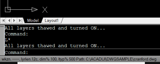
Press L* <enter> to turn on and thaw all layers.
Read the status line at the bottom of the screen. It will show you the current Workzone name and layer length setting:
wkzn. 001P01, lyrlen. 12chr, or something similar and more.
If the lyrlen is not set to 12chr press F7 until it is. ?????????????????????????????????????????????????????
Press LR <enter> to start Layer Resolve command in Modelspace and note the resulting prompt.
Layers to RESOLVE:
Current DT codes: 001:G, 002:D, 004:S, 008:O, 016:L, 032:H, 064:E, 128:R, 256:F
Enter three digit number or key-letter:/<[001]>/<:label scheme/ALTMENU:>
Press 001 or G explicitly or [spacebar] or <enter> to use/accept the default value 001.
<<ent/sub-ent>>/<[E]>/Enter view-point-code:
Press P
<<ent/sub-ent>>/<[02]>/Enter view-ID-code:
Press 01
Processing...please wait.
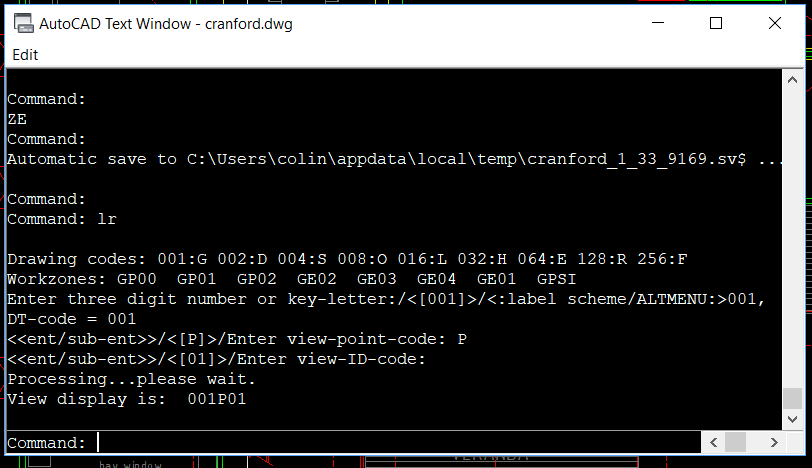
Press ZE <enter> or Z <enter> E
Press LR+ <enter>
You are given a reminder of the current Drawing-type codes and prompted to enter a new three digit code or single character mnemonic.
The drawing is currently resolved into 001GP01 (or GP01) General arrangement Plan level 01. So let’s add level 02.
Command: LR+ <enter>
Layers to ADD:
Drawing codes: 001:G 002:D 004:S 008:O 016:L 032:H 064:E 128:R 256:F
Workzones: GP01 GP02 GP00 GPS1 GSS1 GS01 GP-1
Enter three digit number or key-letter:/<[001]>/<:label scheme/ALTMENU:>001,
DT-code = 001
Press G (or 001)
<<ent/sub-ent>>/<[P]>/Enter view-point-code:
Press P
Enter 2 characters: or tab:>
Press 02
Processing...please wait.
View display is increased by: 001P02
Note that the program only accepts valid entries and prompts to try again if an invalid entry is attempted.
Note the addition of the loft space in the roof. This allows careful checking of structural alignments.